Once the integrity of the kit has been checked, you need to choose the version you want to build from the available options. Nowadays, most kits, even in a 1/72 scale, include alternative parts that allow for the creation of different versions of the same subject. Don’t forget to also choose the decals that suit the chosen version.
As mentioned in previous sections of this guide, it’s important to have good reference material, especially for decoration and insignia. This documentation will also help the most demanding modelers verify the accuracy of the scale. Many enthusiasts carefully document all the errors in the base model to correct them later. In general, a few basic checks are enough (wingspan, fuselage length, dimensions of the fixed surfaces and rudder, wing dihedral, and cockpit position), but it’s still rare for a manufacturer to have made such obvious mistakes. Often, inaccuracies in models come from parts that couldn’t be faithfully scaled down due to their already reduced thickness in the real aircraft: landing gear doors, flaps, ailerons, mast antennas, etc.
The Instructions
The assembly of the model should follow the general sequence suggested by the instructions. If you change the order, you’ll inevitably face parts whose assembly would require dismantling already glued subassemblies, which can be tempting to “forget,” thus compromising the accuracy of the model. In recent kits, most instruction sheets are generously illustrated step-by-step, with a generally concise text. A short caption in multiple languages helps you understand the essentials without resorting to dictionaries or extensive language skills.
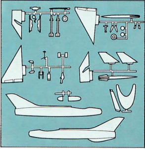
Moreover, the part numbers on the instructions are also printed on the sprues (or inside the parts themselves when their size allows it). Some manufacturers even duplicate the various sprues, which are illustrated and numbered on the instruction sheet. Each part can be easily identified by its number or by comparing the drawings with the sprues. To save time, it’s best to work in subassemblies: for instance, assemble the wings and, while they dry, prepare the fuselage, engines, or cockpit. The method of building multiple models in a “series” is even more efficient, especially for smaller scales, and it saves time: you can paint, for example, all the tires, weapons, cockpits, and instrument panels at once, avoiding the need to take out your painting equipment just to decorate two tires or a single engine, which only takes a few seconds.
Preparing the Parts
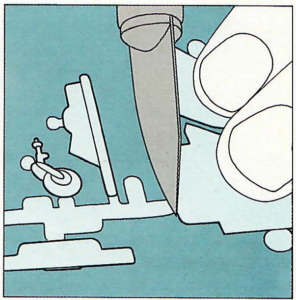
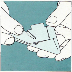
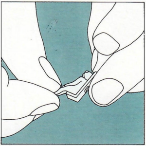
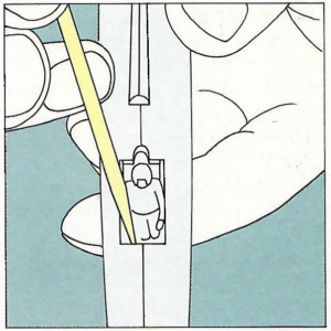
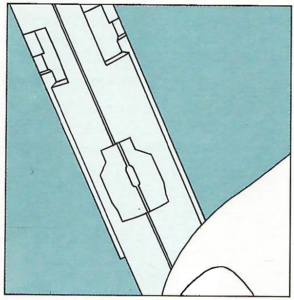
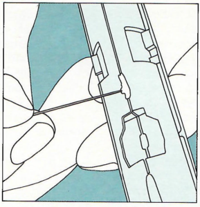
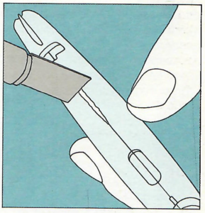
Once the various parts are identified, you can start detaching them from their sprues. Each part should be removed gently, as you need them – it’s crucial not to detach all the parts before assembly, as you could lose them or – more importantly – forget their purpose. Of course, this is only true for the smaller parts.
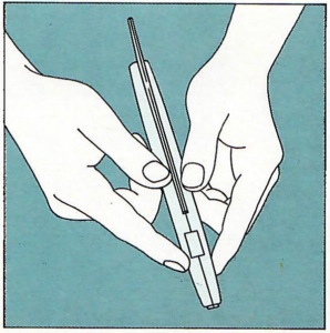
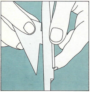
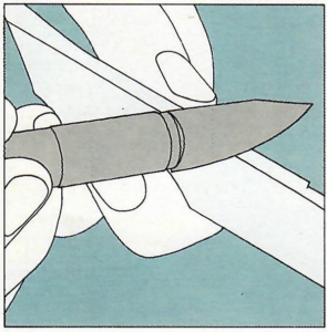
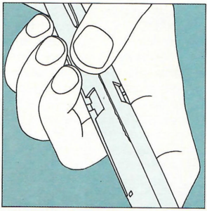
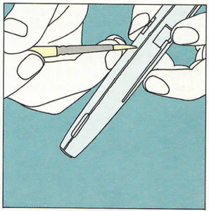
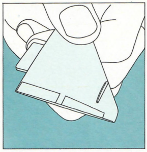
The parts should be carefully removed from their sprues using a modeling knife, pressing it against a flat surface. The small connector joining the part to the sprue should be cut about 1mm from the part itself, not flush; the remaining little protrusion can then be easily trimmed with a knife or sandpaper.
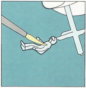
Some small parts are easier to paint while they’re still attached to their sprue: correctly identify these parts before planning the painting stage. The next step in assembly is the dry fit, which involves checking the joints and bonding surfaces to identify and correct any potential asymmetries or distortions that could prevent perfect contact between the parts and might require the later use of filler. A classic example of the benefits of dry fitting is with the two fuselage halves; to ensure perfect contact, they almost always need to be smoothed with files or sandpaper. Dry fitting also helps you familiarize yourself with the assembly sequence and the overall appearance of the completed model. It only takes a few minutes, and it is essential for meticulous assembly. After all, the difference between an ordinary model and a masterpiece lies in small details like these.
Centering
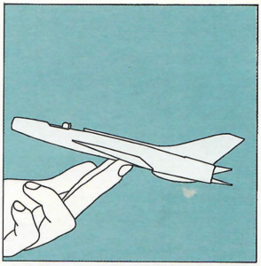
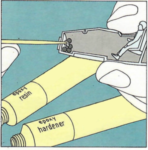
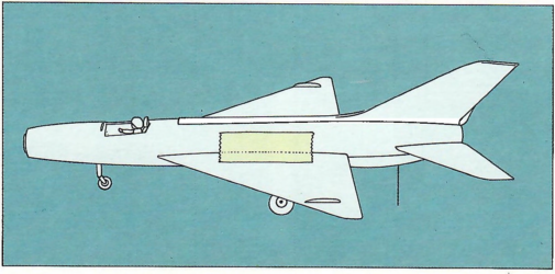
Before gluing the main parts, plan for satisfactory centering of the finished model so that its ground stance matches that of the real aircraft. Aircraft models with tricycle landing gear often tend to tilt upward, as their center of gravity is located too far back. In this case, perform the following steps:
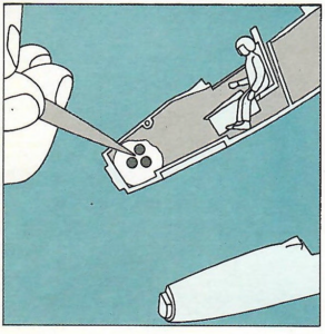
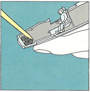
- By using adhesive tape and rubber bands, assemble the fuselage, wings, stabilizers, and any other parts whose weight might affect the balance. Inside the nose, carefully place a few weights and secure them with some putty.
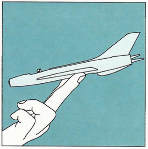
- Next, balance the model on two fingers of one hand, making sure that the attachment points of the main landing gear rest on your fingers.
- Observe the model’s tilt relative to the horizontal plane: if the front, already weighted, points downward, the balance is satisfactory. If, on the other hand, the model pitches up, you’ll need to add one or two more weights to the nose.
- Open the fuselage and glue the weights using a universal adhesive that doesn’t damage the plastic and is especially suited for bonding two different materials.
When the shape of the fuselage (such as a glassed or very narrow nose or extremely fragile landing gear) doesn’t allow for weights to be secured, you can place a “stand” made of steel wire under the rear fuselage to serve as a support. This wire is, of course, not very aesthetically pleasing, but it’s probably better than a model sadly resting on its tail. Alternatively, you can attach a larger weight between the nose and the center of gravity, even if it’s not at the very front, but the required weight will increase proportionally to its distance from the nose.
The Wings
Quite often, the exact dihedral angle is not maintained, especially in small-scale models; this is a very noticeable mistake that needs to be corrected. The same issue occurs with 1/248 scale models when the weight of the wings tends to make them droop. Here’s a way to fix it.
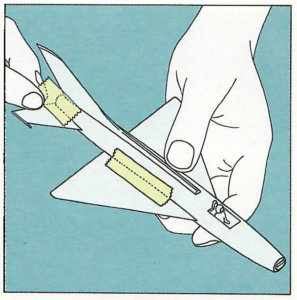
By using a technique borrowed from the construction of flying model aircraft, we build a small scaffolding to support the model during the drying process of the wing-fuselage assembly. Once the dihedral angle value is determined (sometimes explicitly indicated in the instructions), we draw four equal trapezoids on a fairly heavy cardboard, with the upper side having the same dihedral as the wingspan. These trapezoids, once cut out, are glued two by two on a surface as flat as possible. The height and reciprocal distance of these cardboard pieces must be such as to allow the fuselage to fit in the middle.
We then check the dry assembly of the wings and fuselage, glue them, and press the wings onto the supports, with the fuselage in the middle. By securing everything with adhesive tape, the dihedral angle achieved after drying will be accurate and identical for both wings. (See diagram).
The Gluing
We have already discussed the various types of glue and their fundamental characteristics earlier. Now let’s look at their application.
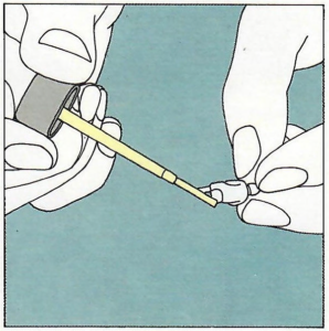
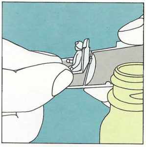
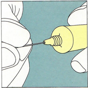
The first rule is to always use as little glue as possible; plastic models are meant to be displayed statically, preferably under glass, and are rarely handled. They are not designed to be particularly strong, and in any case, their sturdiness does not depend on the amount of glue used for assembly. Liquid glue is easier to use, as it is relatively clean and, if of good quality, does not string. Tube glue should not be applied directly from the tube, but with a small brush or a pin. If applied directly from the tube, there are two risks: first, it’s challenging to control the amount properly, and we always end up using too much; second, the natural plug that forms in the tube’s neck is pushed out by strong pressure, resulting in a significant flow of glue. To avoid these drawbacks, it’s better to place drops of glue on non-porous surfaces (cellophane, glass, etc.) and pick up the desired amounts with a pin. Apply the glue in small amounts, avoiding any overflow onto surfaces that are not meant to be glued, as the usual “cement” melts the plastic and damages the engraved details on the parts. Also, take care to squeeze out only one drop of glue at a time, as it dries very quickly and becomes unusable.
After spreading the glue, whether liquid or semi-fluid, it is advisable to wait a few moments before joining the pieces together, allowing the glue to melt just enough plastic, making it easier to bond the parts. This way, we also avoid the formation of an excessively thick layer of glue, which the pressure applied on the two pieces causes to overflow from the joint, damaging the plastic.
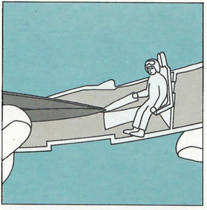
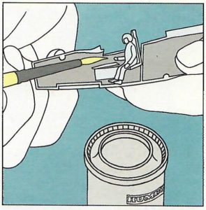
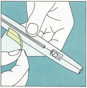
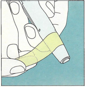
To be on the safe side, especially for large-scale models, there is a longer but much more reliable method. For gluing the fuselage’s half-shells, for example, we perform a dry assembly. Place a bit of tape along the gluing line, then cut the tape along the same line with a knife. Having thus obtained a protective strip along each part, apply the glue; any splashes or overflows of glue will fall onto the tape, which can be easily removed once the gluing is complete.
How long does it take for the glue to dry? There’s no one-size-fits-all answer, as drying time depends not only on the glue itself but also on the quality and type of plastic, the room temperature, and the application method. Generally, a good glue doesn’t take more than fifteen minutes to dry completely, but it stops sticking after just two or three minutes. The easiest way to check is to gently touch the glued part, being extra careful not to damage the model. Indeed, there’s nothing less appealing than a fingerprint on the plastic caused by a glue-covered finger.
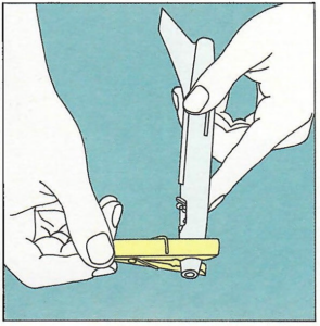
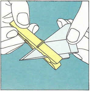
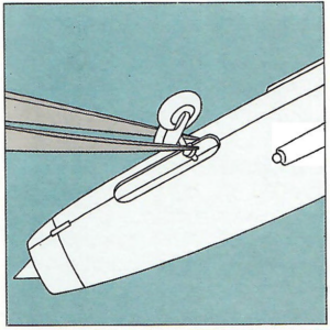
It’s not strictly necessary to apply pressure on the glued parts while they dry, using rubber bands, clothespins, etc., because the bond between the parts is created by the chemical reaction between the glue and the plastic, not by the pressure of the two parts together. On the contrary, too much pressure can result in glue overflow. However, it’s still desirable to keep the parts in the correct position, and in most cases, a little bit of tape is more than enough when finger pressure for a few seconds seems insufficient. For small parts, you can hold them with tweezers while gently blowing on them to speed up the glue-drying process. On the other hand, rubber bands and clothespins are useful for holding larger parts during the fifteen minutes of drying time, and they’re essential if the parts are warped or if they have a difficult connection.
Since glue, particularly the tube variety, dries quite quickly, it can be challenging to apply it evenly. This is the case, for example, when bonding the two half-fuselages on a large 1/24 scale model. With liquid glues, this issue is less significant, but it can still occur occasionally.
A possible solution involves applying glue to the interior of the parts to be joined, expanding the surface of the melted plastic. However, don’t overdo it, or you risk damaging the model. As you might imagine, this method is only feasible if the fuselage has large and numerous openings that allow gluing from the inside. Nevertheless, it’s generally applicable to large-scale models, which are precisely the ones that most often face the initial challenge of uniform bonding.
Putty
Despite preliminary checks, dry fitting, and the use of tape during bonding, cracks may still appear between the parts. In this case, you’ll need to use putty.
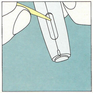
Apply it in small amounts with a pin or toothpick. However, since the putty tends to shrink as it dries, use slightly more than necessary. In other words, it’s not enough to simply fill the crack; you should also allow some overflow above it. Be careful not to go in the opposite direction, though, as you’ll quickly end up with small, dry putty “pancakes” that are difficult to remove.
Let’s recap: apply putty in small amounts, slightly overflowing the crack; let it dry thoroughly (at least overnight) before smoothing with wet sandpaper, using progressively finer grits. If the result isn’t entirely satisfactory, you need to repeat the whole process.
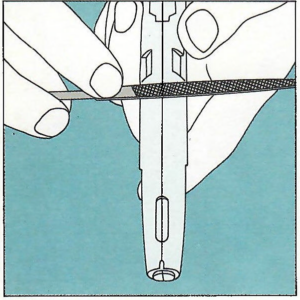
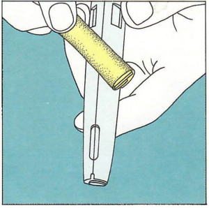
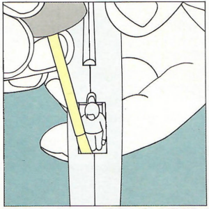
Putty can also be used to fill the hole in the fuselage, which allows for displaying the plane “in flight.” Generally, these stands allow for varying display options, but they’re not very stable, and a model can easily be damaged beyond repair if its stand fails. Given its size, this hole can’t be filled with putty alone since it shrinks as it dries, creating a slightly concave surface. It’s recommended to cut a custom piece of plastic from a sprue, glue it inside the hole, and cover it with putty, proceeding as described above for cracks.
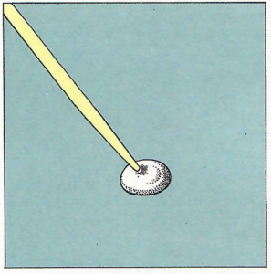
You can also use putty to create any necessary accessories for a complete model finish (which aren’t always included in the kits) or to enhance the appearance of details such as pilot seats, instrument panels, control sticks, rudder pedals, flettner tabs, etc. To work with the putty, roll a drop between your fingers to form a small, malleable sphere, which can be easily shaped and, once dry, can be carved or filed like plastic.
Putty usually needs to be painted once dry, using the same color as the surrounding plastic parts. This way, once repainted, it won’t reveal any difference in the base color.
Correcting Imperfections
It’s quite common for model kits on the market to be imperfect: industrial requirements, lack of documentation, and the need for easy assembly force model kit manufacturers to make certain compromises with reality and scale accuracy. Therefore, all kits have minor imperfections that the model builder should correct. Of course, we’re not talking about glaring errors, such as wings that are too small or too large or incorrect shapes; we’re referring to imperfections like the overly pronounced riveting, thickness of the leading or trailing edges of wings, or overly thick canopy frames.
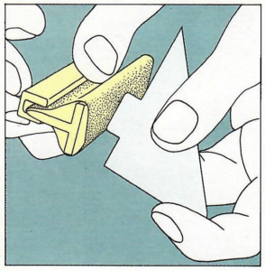
The flaws and minor errors encountered during the initial examination of the model or during dry-fitting should be eliminated as soon as the piece to be modified has taken its final shape. In the case of a wing, for example, the two halves (upper and lower) must be joined before making corrections. If the wing is molded in one piece, modifications can be made immediately using a knife, file, and sandpaper.
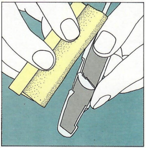
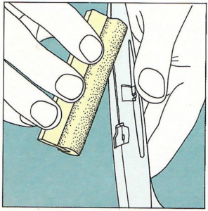
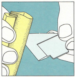
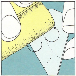
- Edges of wings and stabilizers: Due to the techniques generally used for printing parts, leading and trailing edges are often too thick. Excessive thickness can be reduced using sandpaper, always mounted on a suitable handle: if you hold the paper between your fingers, you risk creating an uneven surface, making it even less successful. Gently and carefully sand, being cautious not to damage the details on the wing.
- Rivets and panels: In reality, airplanes have worn surfaces, especially after a few months of intense activity; likewise, their construction usually doesn’t involve the meticulous attention to detail that characterizes a true modeler. On the other hand, model kit manufacturers tend to exaggerate the details of the aircraft’s coating due to manufacturing reasons. Looking at the details of an average model, one might think an airplane is a crudely assembled collection of metal sheets held together by rivets and bolts several centimeters large! Overemphasized rivets can be toned down using a very fine, wet abrasive paper. Panels that are too deep or too wide can be partially concealed by an initial coat of paint or a layer of thinned putty.
On the contrary, insufficiently pronounced panels and sheet metal cutting lines can be accentuated – even drawn – with a very fine and sharp-tipped knife. Be sure to verify the location of the details to be marked using documentation beforehand; it is also easier to trace the details with an ordinary black pencil before “engraving.”
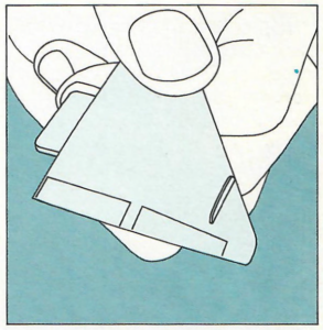
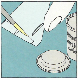
- Control surfaces: To properly emphasize their presence, the cracks representing the junction between fixed wings and ailerons and rudders are deeply engraved. Often, this is done with exaggeration: consider that a 0.2mm wide line on a 1/72 scale model (barely visible) actually corresponds to a 14.4mm wide “crevasse” on the real aircraft. Therefore, it’s necessary to tone down these overly pronounced details by first using abrasive paper, followed by applying a thick initial coat of paint. For this purpose, an opaque gray enamel – a neutral shade by excellence – is particularly suitable.
With 1/24 scale models, however, we often encounter the opposite problem, which is inadequately defined details. In this case, you can either emphasize the existing details by retracing them with a knife or carefully cut out the parts and then glue them back into place. When cutting, even with a very sharp knife, you’ll inevitably remove some plastic, which might result in an exaggerated gap. You’ll then need to fix this with putty or apply a thick layer of paint. At first glance, this technique seems like a vicious cycle, but in reality, it’s not, especially if you use glue generously. This doesn’t contradict the earlier advice about using glue sparingly; always proceed with care, in small amounts, and be sure to cover the parts with tape. The small (and we mean small) excess of glue, by melting the plastic, will reduce the gap’s size. Lightly tracing the gap with a pin removes a bit of glue while recreating the characteristic grooves along the edges of control surfaces.
However, this cutting method is not recommended for 1/72 scale models unless you’re masters of knife and glue handling since such modifications aren’t absolutely necessary at such a small scale.
- Rudders and elevons: The above advice, of course, applies to rudders. In the case of elevons, meaning when fixed wings serve as stabilizers, there’s only a slot at the separation with the fin that needs to be emphasized or – if it doesn’t exist – created by cutting or engraving the plastic.
- Landing gear: Landing gears are usually simplified on small-scale models, and given the limited size, it might not be worth the effort to highlight details that probably won’t be seen. However, it’s crucial to check the landing gear’s length, as its accuracy can affect the credibility of the entire model.
You’ll find tips for assembling landing gears elsewhere, which use the same structures that were used for the wing dihedral. We’ll emphasize here the importance of studying comprehensive documentation, which will provide essential information to replicate the aircraft’s exact ground stance.
When you look at real aircraft photos, you can see the variation in landing gear length depending on the conditions: on the ground, the shock absorbers are in their normal compression phase; during landing, at the moment of wheel touchdown, they are compressed to their maximum travel, whereas after takeoff, they are at their maximum length. Since it’s challenging to know which of these three positions the model manufacturer chose, the modeler must verify the correct length themselves, remembering that if the aircraft is depicted stationary on the ground, the landing gears should be slightly shorter than the wells they retract into.
- Wheel well doors: Sometimes, on 1/72 scale models, the wheel well doors are missing, and you certainly can’t hide this omission by painting them black. In this case, you’ll need to cut out the section corresponding to the doors using a saw: if the wing is in two parts, only the lower surface will be cut, of course. Once the well is cut out, reduce its thickness by sanding it; similarly, file the edges of the well to reduce its thickness as well. The cut and filed part will then be glued back inside the well; it will be smaller than the hole since some plastic will have been “eaten away” while cutting. Fill the gap with filler, let it dry, and then finish with sandpaper.
During the cutting and filing process, be very cautious not to cut the landing gear attachment itself, as this may result in a shorter landing gear height once assembled. If it’s impossible to avoid cutting the attachment, fix the issue by using a piece of sprue sufficiently filed down.
- Canopies and transparent surfaces: The main flaw of these parts, especially on 1/72 scale models, is the excessive thickness of the plastic; this is also the most difficult issue to correct. Highly experienced modelers often use plastiglaze, which they work with themselves, to replace the canopies included in the kits. However, this is a rather complicated solution and is not recommended for beginners. Generally, there’s no alternative: you must keep the original canopy without giving in to the temptation of filing it down from the inside to reduce thickness. Nonetheless, you can significantly improve the final result by paying extra attention to the canopy’s markings and paintwork. Indeed, it’s better to have a well-mounted and well-decorated canopy (which often distinguishes a “second-class” model) than a model with an ordinary canopy, even if it has a more accurate thickness. If the canopy – as is usually the case – already has the framework molded in relief, you can proceed as follows:
- Cover the entire canopy with adhesive tape, carefully sticking it to the canopy.
- Use a knife to cut the tape over the framework, exposing only the areas to be painted. At this point, if the framework is too large – which is common – only uncover the central part of the framework, carefully calculating their width according to the model’s scale.
- Check the tape’s adhesion, looking for raised points or air bubbles on the plastic, which could allow paint to seep in.
- You can now paint the exposed framework after attaching the canopy to the model.
- Once the painting is complete, remove the pieces of tape: the canopy’s framework, with the desired thickness, is painted without any smudges.
For projects like these, which require very straight edges, it’s best not to use Maskol, as although it’s quite suitable for other tasks, it doesn’t guarantee straight lines. If the canopy doesn’t have the framing engraved, it’s better to use another technique.
- Purchase self-adhesive sheets from a stationery store. These come in a wide variety of colors, and you can cut out some strips of the required width (once again, quick calculations using the scale come in handy).
- If the paper is already the right color (and here, you’ll need to use reference materials), apply it directly to the canopy, following the guidelines provided by the same documentation. If the color isn’t suitable, place the paper strips on a flat surface and paint them. Once dry, apply these strips as described above.
If you can’t find suitable self-adhesive paper, you can always use tape:
- Stick a few centimeters of tape onto a flat surface.
- Paint the tape strip the desired color.
- Cut the tape with a knife, being mindful of its thickness, and using a metal ruler for guidance.
- Peel off the tape and reapply it to the canopy.
Regardless of the method used, it’s always better to have strips longer than necessary, so you can trim the ends and ensure better adhesion of the central part. To achieve even better and longer-lasting adhesion, you can apply a thin layer of clear paint over the canopy once these steps are completed. Indeed, the framework will become as glossy as the rest, but that’s one of the compromises you’ll need to accept.
- Propellers: Model kit manufacturers have always taken pride in offering rotating propellers, using more or less complicated systems of pivots, axles, and spinners (this is also true for the wheels of landing gear). However, a plastic model is, by definition, meant to remain stationary: why make life complicated by making a propeller spin with the slightest breeze? From all perspectives, including those considering a potential relocation or periodic cleaning, a fixed propeller seems the most interesting solution. Before gluing it, though, don’t forget to determine its most typical position using any available photos.
- Wheels: Generally well-detailed for larger scale models, wheels are often overlooked in 1/72 scale models, perhaps due to the choice of landing gear position (raised or lowered) left to the modeler. The main flaw of plastic-molded wheels comes from the impression of rigidity caused by overly uniform tire sidewalls, with tires being equally rounded at the top and bottom, while in reality, a tire is always flatter where it contacts the ground.
Once the model is assembled, and the correct stance is established, it is usually sufficient to gently rub the wheel on sandpaper to flatten the part touching the ground, without making it completely square. Afterward, the paint can be easily replaced by touch-up.
- Pilots: The decision to include or exclude a pilot in the model is related to the issue of the canopy. Each person can decide for each model, as there’s no general rule; however, since the planes are depicted on the ground, it’s unclear why there would be a pilot inside. Of course, this isn’t true when you want to place the finished model in a diorama that might represent, for example, an airfield scene with a pilot, mechanics, ground equipment, etc. In any case, a pilot obscures a large portion of the cockpit details, and thus may sometimes serve a purpose.
- Engines: Generally, the only visible engines (and even then, only partially) in a model are air-cooled radial ones. The others are hidden beneath cowling or within fuselages. If we focus on smaller scales (larger scales indeed make it easier to replicate engine details), the detail that is most often missing is the absence of distributor caps, which can be represented by small metal (copper or steel) or plastic wires. These wires, attached in pairs to each cylinder, should be glued to the central part of the engine, which is visible through the cowling. By applying a drop of glue to the cylinder heads, you can also create the appearance of their covers. You can then enhance the realism of the engines by carefully painting them.
- Position lights: Often overlooked on smaller models, position lights, which have been present on all aircraft since the last war, add extra realism to the model. If they’re not included, you can create them using small pieces of plastic cut from the sprues of transparent parts (canopies, portholes, etc.), shaped and glued in their exact locations. First, using the lights mounted on the wings as an example (green on the right, red on the left), create small housings in the wings with a file (they are marked in the plastic, or you can find their exact position by consulting your documentation). Next, shape the transparent plastic pieces, and then glue them in their housings, after painting their back surface red or green. Once the glue is thoroughly dry, refine the profile of these pieces, and restore their shine by lightly sanding them with very fine abrasive paper. Finish by applying a light coat of clear gloss. Naturally, these steps should be performed before painting the wings; during the final paint job, you’ll cover the lights with Maskol.
Landing lights, equipped on all modern aircraft and often overlooked by manufacturers, can be created just as easily. To do this, use the small “lenses” from the transparent sprues, paint them silver, and then glue them to the designated location. Quite often, these “lenses” are present on the sprues; so it’s worthwhile to keep them anyway, even if you don’t have an immediate use for them, as it’s better to use them later than to make a part of this kind from a small block.
- Cockpits: The days of being satisfied with models that roughly reproduced the fuselage profile and canopies that covered a pilot’s torso are long gone. The modern modeler demands accurately reproduced cockpits, at least in their essential components: instrument panel, consoles, walls, seat, and main controls. However, given, once again, the small size of many models (especially at 1/728 scale), these details sometimes leave something to be desired and require careful and comprehensive elaboration. Because it’s the details that make a model stand out.
Undoubtedly, one cannot claim to accurately replicate an entire airplane cockpit unless they are a true miniaturist: a glance at the photo of a modern airplane’s cockpit clearly demonstrates the futility of such a task. Often, it is sufficient to recreate the details that represent the overall cockpit layout. Therefore, we can streamline the essential details to include in a cockpit by dividing model aircraft into three somewhat arbitrary categories:
- 1930s-era airplanes (and up to the last biplanes). Cockpits are usually open, featuring wooden seats, a very basic dashboard, a control stick, and a few controls (flaps, trim, etc.) on the sides of the seat. The fuselage structure can also be seen on the inner sides of the cockpit.
- World War II-era airplanes (and up to the first jet aircraft). Dashboards are more comprehensive, with some controls (radio, engines, etc.) mounted on side consoles, seats are sturdier, often armored; the cockpit sides are closed by panels, also armored, while the cockpit itself is generally enclosed by a canopy.
- Modern jet aircraft: The pilot is completely surrounded by controls and instruments, indicators, levers, and buttons; they sit in an ejector seat of extraordinary complexity.
From a modeler’s perspective, these three categories represent three different levels of finishing. For models in the first category, it’s enough to sketch the seat and dashboard with small plastic or very thin cardboard panels: the structure is replicated by gluing pieces of wire or heated, stretched plastic inside the fuselage. Similarly, the control stick can be represented by a small piece of plastic that can be shaped using a heated pin. The finishes of the second-category airplanes aren’t much more difficult since the canopy, once glued, will conceal most of the cockpit details. However, with modern jet aircraft, the canopy is typically large and made of a single piece, allowing a view of the cockpit interior. If the model doesn’t provide for it, it’s possible to build the missing parts: create the side consoles with a few small strips of plastic, which can also be used for the cockpit sides, floor, and dashboard. The ejection seat can be crafted from a small block of lightweight wood, or with putty; the control stick can be represented by a pin or, better yet, a toothpick that can be carved using a very sharp knife.
Of course, these tips don’t apply to large-scale models, which include all the necessary parts for detailed elaboration; however, we’ll see later how to improve their presentation.

